
450 HP XLD 1250A 208V NEMA 1
Buy New -
What We Offer


Product Information
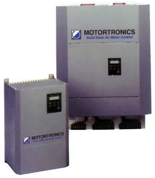
450 HP XLD 1250A 208V NEMA 1
Tech Specs
Back To Top| Amperage | 1250 Amp |
|---|---|
| Condition | New |
| Frequency | Ac 50-60Hz |
| Manufacturer | Motortronics |
| Pole/Phase | 3 Phase |
| Voltage | 208V |
The Southland Advantages
Proud Family Run Business
Southland Electrical Supply has been in business for nearly 30 years, building a reputation for quality products at a reasonable price. Our inventory is far more extensive than what can be represented on our web site, so please call one of our knowledgeable salesmen with your specific needs.

Buy With Confidence

Industrial Electrical solutions are not one-size-fits-all. We will custom design, engineer, upgrade or retrofit a solution tailored to fit your needs.
Call us Today

Industrial Electrical solutions are not one-size-fits-all. We will custom design, engineer, upgrade or retrofit a solution tailored to fit your needs.
Call us Today
Average order time for Molded Case Breakers is 1 - 2 days for common designs and most Molded Case projects are completed in 1 - 2 weeks, which means less downtime.
Call us Today
6 locations across the southeast, an inventory of over 200,000 square feet and our extensive vendor network ensures we can help you find exactly the right product.
Call us Today

We offer field service and preventative maintenance support for all products we supply. We provide shut down and after hours services for low and medium voltage equipment as well.
Call us Today